
Strange TVRD Results
QUESTION: I use the TVRD command to get a screen dump from a window. But people are starting to complain about my programs because the colors of images from these screen dumps are totally messed up. The programs work fine on my machine. What is going on?
![]()
ANSWER: Most of us started programming IDL when the very best machines were capable of displaying only 256 colors. These days well over half of us are programming on machines capable of displaying thousands or millions of colors and programming techniques that used to work for us no longer work the way they used to. The TVRD command is a good example.
My guess is that the people having trouble with your TVRD commands are people running your programs on 16-bit or 24-bit color displays. On these kinds of machines, there are three image planes that need to be read (corresponding to the red, green, and blue values that make up a pixel color) to get a screen dump from a graphics window. This is different from an 8-bit display, which has only a single image plane to read.
This command:
image2D = TVRD()
works fine on an 8-bit display because the pixel values that are returned are used as indices into the color table. For example, if the pixel return value is 2, then the pixel is displayed with the color triple (R[2], G[2], B[2]), where R, G, and B are the color table vectors. If these numbers were, for example, 255, 128, and 0, respectively, then that pixel would be displayed with an orange color.
But if you were running IDL on a 16-bit or 24-bit display, it is not the color table index number that is returned, but the maximum value of the values in the the color table vectors.
pixel_value = Max( [R[2], G[2], B[2]] )
What this means to you is that the TVRD command above would return a value of 255, not the value of 2 that you expected. (Note that this is as true of a pixmap window as it is of a normal IDL graphics window.) Of course, if you plan to use the image as if it had a value of 2, you would find your colors very strange indeed.
What Can Be Done?
This naturally brings up the question of what can be done about this situation. Well, you have some choices.
First of all, you could use the True keyword with the TVRD command if you are on a 16-bit or 24-bit display. This causes the command to read all three image planes correctly. For example, you could write code like this:
   Device, Get_Visual_Depth=thisDepth
   IF thisDepth GT 8 THEN image = TVRD(True=1) ELSE image = TVRD()
The only problem with this method is that the resulting image that comes back when on a 16-bit or 24-bit display is a 24-bit image, not an 8-bit image like you may be used to. And, of course, 24-bit images have to be displayed with the True keyword to the TV command if they are to be displayed correctly. So code that uses this return image will have to be written like this:
   Device, Get_Visual_Depth=thisDepth
   IF thisDepth GT 8 THEN TV, image, True=1 ELSE TV, image
Note that the TVImage program, which is a replacement for the TV command, does this automatically depending up whether an 8-bit or 24-bit image is being displayed. It also automatically sets the correct color decomposition keyword on the Device command, which is a further complication, since color decomposition must be on or the gray-scale color table must be loaded to display a 24-bit image accurately on a PC platform. (See the tip on displaying 24-bit images for more details.) In other words, the correct commands for a PC platform are really these:
   Device, Get_Visual_Depth=thisDepth
   IF thisDepth GT 8 THEN BEGIN
	Device, Get_Decomposed=thisState, Decomposed=1
      TV, image, True=1
      Device, Decomposed=thisState
   ENDIF ELSE TV, image
(This automatic setting of the correct keywords makes the TVImage program just about the most useful program I own, not to mention its other capabilities.)
[Editor's Note: After this article was written, I wrote the program TVRead to be the complement of TVImage. That is, whereas TVImage will set the appropriate True keyword depending upon the depth of the visual when the image is being displayed, TVRead will do the same when reading an image from the display. Used in combination, you will always get the proper visual display. TVRead can also automatically prepare an image and its color table for saving the image into any number of output formats. This saves you from having to worry about the Color_Quan problems discussed below.]
Using the Z-Graphics Buffer
Another alternative is to use the Z-Graphics Buffer to display graphics that you wish to read with the TVRD command. The Z-Graphics buffer is guaranteed (at least through version 6.3 of IDL) to be a single image plane window. (Editor's Note: as of IDL 6.4, the Z-buffer is capable of being set in 24-bit mode. The explanation below only pertains to the default 8-bit mode on versions starting with IDL 6.4.] Your code might look like this if running on a machine with a 24-bit display:
   displayimage = LoadData(7)
   thisDevice = !D.Name
   Set_Plot, 'Z'
   Device, Set_Resolution=[360, 360]
   LoadCT, 33
   TV, image
   snap = TVRD()
   Set_Plot, thisDevice
   Device, Decomposed=0
   Window, XSize=360, YSize=360
   LoadCT, 33
   TV, snap
Of course, not all of us write our programs so that they are device-independent, so many of our display programs won't work in the Z-Graphics Buffer, for a variety of reasons. If that is the case, then there are not many alternatives left.
Using Color_Quan to Create a 2D Image
One technique you might try is to use the Color_Quan command to create a 2D image, and the appropriate color table vectors to display it with, from the 3D or 24-bit image you get from TVRD.
The code for that technique looks like this:
   Device, Get_Visual_Depth=thisDepth
   IF thisDepth GT 8 THEN BEGIN
      image3D = TVRD(True=1)
      image2D = Color_Quan(image3D, 1, r, g, b)
      TVLCT, r, g, b
   ENDIF ELSE image2D = TVRD()
   TV, image2D
The only drawback to this technique, and it can sometimes be a large one, is that the color table vectors that are returned from Color_Quan don't normally look anything like the color vectors you are used to working with in IDL. Below is an example of what the color table looks like at the time the TVRD command is executed and what it looks like after the color vectors returned from Color_Quan are loaded.
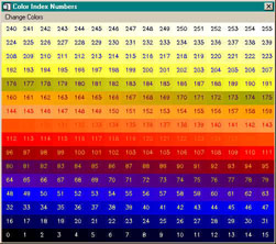
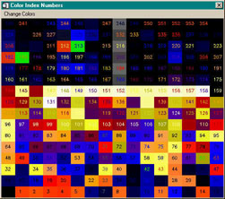
![]()
Last Updated 11 June 2007